How to Manage Condensation on Glass Walls: Expert Engineering Guide
The expansion of structural glass facades in both contemporary homes and commercial high-rises has fundamentally shifted how architects and engineers approach building physics. Where glass was once considered a simple, inert barrier between interior and exterior spaces, it now functions as a complex thermodynamic filter. How to Manage Condensation on Glass Walls. Managing the balance between indoor comfort, visual transparency, and environmental durability requires an analytical approach to envelope design. When cold exterior temperatures meet warm, humid indoor air, phase change occurs, creating an operational and structural challenge.
Understanding how to manage condensation on glass walls requires a firm grasp of psychrometrics, heat transfer, and material science. When design or construction teams miscalculate the dew point or ignore the effects of thermal bridging, the consequences extend far beyond simple visual obstruction. Chronic condensation leads to the degradation of structural silicone sealants, the rusting of steel components, and the growth of toxic mold behind interior finishes. This guide deconstructs the structural mechanisms, system variations, testing methodologies, and economic variables that govern moisture control in large-span glazing systems.
By examining the physical reality of glass assemblies, this manual provides a clear, actionable methodology for specifying assemblies that remain safe, clean, and thermally efficient for decades. The goal is to design the envelope to keep surface temperatures above the dew point, controlling the aqueous environment without relying on temporary, inefficient mechanical fixes.
Understanding “how to manage condensation on glass walls”
When professionals investigate how to manage condensation on glass walls, they must treat the facade as an integrated thermodynamic system rather than a collection of independent panels. Condensation occurs when warm, moisture-laden air comes into contact with a surface that is at or below the dew point temperature. The liquid water that forms is not just a maintenance issue; it is a clear indicator of a thermal imbalance within the envelope assembly.
A common misunderstanding during the early design phases is the assumption that adding more layers of glass will solve any condensation problem. In reality, if the perimeter framing system contains highly conductive aluminum profiles that create a continuous thermal bridge to the outside, moisture will collect along the edges of the frame, regardless of the performance of the center of the glass. Therefore, knowing how to manage condensation on glass walls requires addressing the frame, the insulating glass unit (IGU) edge seals, and the surrounding building air barrier simultaneously.
The primary goal of the designer is to ensure that the interior surface temperature of the innermost lite remains higher than the dew point temperature of the interior air under worst-case winter conditions. This performance metric is expressed as the temperature index ($T_i$). If the temperature index of the system falls below the local design threshold, the wall will experience localized condensation, leading to moisture damage within the wall cavity.
Deep Contextual Background: System Evolution
The development of moisture management in glass architecture began with the invention of the sealed insulating glass unit in the mid-twentieth century. Before this innovation, single-pane glazing was the standard for all construction types. The interior surfaces of these single panes were almost always cold enough to generate condensation during the winter months, leading to interior water collection and structural rot in adjacent timber window frames.
The introduction of hermetically sealed double glazing in the 1950s and 1960s allowed designers to keep the interior pane at a higher temperature, which reduced the incidence of surface condensation. However, these early designs suffered from premature seal failure and conductive edge spacers made of aluminum, which created a cold perimeter ring around the glass lite. This “cold-edge” effect caused condensation to form in a distinct band around the perimeter of the unit.
The development of warm-edge spacer technology in the 1990s represented a significant improvement in moisture control. These spacers are made of low-conductive materials like structural plastics or stainless steel, which reduce heat loss at the perimeter. Today, modern envelope technology relies on double and triple IGUs filled with inert gases, such as argon or krypton, combined with double low-emissivity (Low-E) coatings. These makeups keep the interior surface temperature close to the ambient room temperature, even during extreme winter conditions.
Conceptual Frameworks and Design Models
To analyze moisture movement and phase change within the building envelope, experienced engineers use several core frameworks:
-
The Psychrometric Phase-Change Model: This framework plots the state of the indoor air against its temperature and relative humidity. It calculates the precise dew point at which water vapor transitions into a liquid state on a cold glass surface.
-
The Thermal-Bridge Continuum: This model focuses on heat flow through the most conductive elements of the facade, such as structural fasteners, anchors, and aluminum mullions, predicting where surface temperatures will drop below the dew point.
-
The Glaser Diagram Method: A graphical analysis tool used to evaluate the potential for interstitial condensation within the cross-section of a multi-layer wall assembly, ensuring that moisture can escape without accumulating in the insulation layer.
Technical Classifications and System Variations
Understanding the differences between the technical makeups used to manage moisture requires analyzing the internal configuration of the glass and framing systems.
Classification of Condensation-Resistant Systems
| System Category | Makeup Description | Thermal Performance | Best Application | Trade-Offs & Vulnerabilities |
| Monolithic Single Glazing | Single lite of annealed or tempered glass | High U-value, very cold interior surface | Unheated porches, interior dividers | Severe condensation, low thermal comfort |
| Standard Double IGU | Two lites with aluminum spacer and air fill | Moderate U-value ($U \approx 2.7 \text{ W/m}^2\text{K}$) | Mild climate residential | Edge condensation in freezing weather |
| Warm-Edge Double IGU | Two lites with polymer spacer and argon fill | Improved U-value ($U \approx 1.4 \text{ W/m}^2\text{K}$) | General residential building | Susceptible to seal failure over long periods |
| Triple-Glazed IGU | Three lites with two low-E coatings, argon fill | Very low U-value ($U \approx 0.6 \text{ W/m}^2\text{K}$) | Cold climate supertall buildings | Heavy load, thick profile, reduced light transmission |
| Heated Structural Glass | Laminated glass with embedded conductive wires | Surface temperature actively held above dew point | High-humidity spas, pool enclosures | High energy usage, complicated wiring at nodes |
| Closed-Cavity Facade (CCF) | Pressurized dry air circulating inside the cavity | Extremely low U-value, no interior condensation | Supertall commercial facades | High maintenance cost, complex air supply system |
| Thermally Broken Curtain Wall | Aluminum frames separated by polyamide struts | Prevents thermal bridging through the metal | High-end homes and commercial use | Requires proper installation to avoid gaps |
Choosing the appropriate system variation requires careful decision logic. For instance, an engineer designing a high-humidity indoor pool enclosure must know how to manage condensation on glass walls without letting water pool on the frame. In this case, specifying a heated structural glass makeup is the most effective choice because it raises the temperature of the interior glass surface directly, preventing condensation regardless of the indoor humidity level.
Detailed Real-World Scenarios and Decision Logic How to Manage Condensation on Glass Walls
Scenario A: The High-Humidity Bathroom Wall
A large master bathroom in a modern home features an expansive floor-to-ceiling structural glass wall that overlooks a cold winter landscape.
-
The Constraint: The indoor air has a high relative humidity (65%) during and after showers, and the exterior temperature drops to 5 degrees Fahrenheit.
-
Decision Point: The designer must choose between a standard double-glazed IGU with aluminum spacers and a triple-glazed warm-edge IGU with a continuous thermal break.
-
Analysis of Options:
-
Option 1 (Standard IGU): The interior glass surface temperature drops below the dew point of the room, causing constant water running down the face of the glass and rotting the adjacent timber floor.
-
Option 2 (Triple-Glazed Warm-Edge IGU): The warm-edge spacer and third lite keep the interior surface temperature above the 52-degree Fahrenheit dew point, preventing condensation.
-
-
Second-Order Effect: The thick triple-glazed unit requires a deeper frame profile, which alters the sightlines of the window wall and increases the dead load on the concrete structure.
Scenario B: The Sloped Skylight in an Atrium
A large, sloped glass skylight over a commercial atrium experiences chronic condensation during the winter months.
-
The Constraint: The warm, moist air inside the atrium rises and collects at the highest point of the sloped glazing, creating large water drops that fall onto the surfaces below.
-
Decision Point: Should the team install mechanical air diffusers to blow warm, dry air across the glass, or replace the skylight with an actively heated structural glass system?
-
Analysis of Options:
-
Option 1 (Mechanical Air Diffusers): The diffusers create significant noise and consume high amounts of fan energy, while failing to solve the underlying temperature differential.
-
Option 2 (Heated Glass System): The system uses an invisible conductive coating on the inner lite to warm the glass surface above the dew point.
-
-
Failure Mode Analysis: Heated glass consumes substantial electricity, requiring a dedicated power circuit and control system to prevent overheating.
Scenario C: The Storefront Glazing in a Humid Coastal Climate
A commercial storefront in a tropical coastal city experiences condensation on the exterior surface of the glass during early summer mornings.
-
The Constraint: The air conditioning inside the building cools the interior glass surface below the dew point of the warm, humid outdoor air.
-
Decision Point: Should the team adjust the indoor thermostat, or add an exterior low-E coating to the glass makeup?
-
Analysis of Options:
-
Option 1 (Adjust Thermostat): Raising the indoor temperature to reduce the difference between indoor and exterior glass temperatures compromises user comfort.
-
Option 2 (Exterior Low-E Coating): The coating limits heat transfer through the glass, keeping the exterior surface temperature close to the outdoor air temperature.
-
-
Second-Order Effect: Exterior coatings can cause temporary visual iridescence under certain light conditions, which can lead to aesthetic concerns from the building owner.
Scenario D: The Unitized Facade with Interstitial Condensation
An apartment building features a unitized curtain wall where interior water damage is observed within the spandrel zones.
-
The Constraint: The vapor barrier was installed incorrectly on the warm side of the insulation, allowing warm, humid indoor air to enter the wall cavity and condense on the cold concrete slab edge.
-
Decision Point: Should the team inject foam insulation into the spandrel cavity from the outside, or strip the interior finishes to repair the vapor barrier?
-
Analysis of Options:
-
Option 1 (Inject Foam): This fixes the immediate problem but traps existing moisture against the concrete, accelerating spalling and corrosion.
-
Option 2 (Repair the Vapor Barrier): The team removes the interior finishes, cleans the concrete surface, and applies a continuous, vapor-tight membrane.
-
-
Compounding Risk: The repair process is noisy and disruptive to residents, requiring temporary relocation during the work.
Planning, Cost, and Resource Dynamics
The financial framework of a facade project is sensitive to design oversights regarding moisture control. When common structural errors are corrected during the construction phase, the costs can be many times higher than if the issue had been caught during the early engineering review.
Estimated Cost Variance of Remediation
| Phase of Discovery | Cost Factor (Multiplier) | Primary Cost Drivers |
| Concept / Design Phase | 1.0x | Modified IGU specification, warm-edge spacers |
| Fabrication Phase | 3.0x – 5.0x | Remanufacturing of lites, modified extrusion dies |
| Construction Phase | 12.0x – 25.0x | Scaffolding, crane rentals, IGU replacement |
| Post-Occupancy Phase | 60.0x+ | Mold remediation, interior finish repair, litigation |
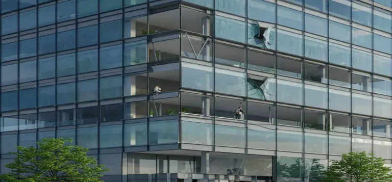
Opportunity costs are prevalent in this market. Choosing large-format glass lites often requires specialized hoisting equipment and street closures during installation. Furthermore, if a lite breaks during construction, the replacement lead time for custom-tempered or bent glass can delay the entire project schedule by several months.
Tools, Strategies, and Technical Support Systems
To design with the best options and manage moisture, facade engineers use several analytical and testing platforms:
-
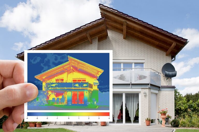
Thermographic Cameras: Used to detect areas of high heat loss and identify thermal bridges around window frames and spandrel zones.
-
Psychrometers and Data Loggers: Tools placed in the building to monitor relative humidity and indoor air temperature in real time.
-
LBNL Window/Therm Software: Used to determine the center-of-glass and overall U-values, solar heat gain coefficients, and condensation resistance index of the assembly.
-
Full-Scale Environmental Chambers: Used to test full-scale mock-ups of facades under simulated interior and exterior temperature extremes to observe condensation formation.
-
Heat-Soak Ovens: A quality-control process that exposes tempered glass to elevated temperatures to force the failure of lites with nickel-sulfide inclusions before they are shipped to the site.
-
Acoustic Testing Chambers: Used to verify the sound transmission class (STC) rating of the structural assembly in noisy urban environments.
-
3D Laser Scanning: Used to survey the as-built concrete frame, allowing the fabrication dimensions to be adjusted before the glass arrives on-site.
The Risk Landscape: Structural Vulnerabilities and Failure Modes
Understanding the risk landscape and identifying the compounding failure modes is critical when learning how to manage condensation on glass walls.
-
Thermal Bridging via Aluminum Frames: When a highly conductive frame element connects the interior and exterior environments, the interior metal temperature drops below the dew point, resulting in localized water collection.
-
IGU Seal Failure: The loss of the hermetic seal allows moist air into the gap between the lites, causing condensation to form inside the unit where it cannot be wiped away.
-
Interstitial Vapor Migration: Warm, moist interior air penetrates through cracks in the interior drywall, bypassing the vapor barrier and condensing on cold structural framing.
-
Silicone Reversion: The chemical degradation of structural silicone joints caused by constant exposure to liquid water, leading to a loss of load-bearing capacity.
Governance, Maintenance, and Long-Term Adaptation
A structural glass facade requires a formal governance structure and a dedicated maintenance schedule to achieve its intended 30-to-50-year design life.
The Layered Maintenance Checklist:
-
Bi-Annually: Wash the glass and inspect the exterior silicone seals for signs of cracking or detachment.
-
Every Five Years: Perform a detailed pull-test or inspection of the structural silicone joints and mechanical nodes.
-
Replacement Triggers: Replace any insulating glass unit that shows signs of internal condensation, which indicates a failure of the primary edge seal.
-
Documentation and Records: The facility manager must maintain a digital log of the makeup, batch number, and installation location of every glass lite.
Measurement, Tracking, and Evaluation
Assessing the performance of a structural glass system requires both quantitative and qualitative methods:
-
Leading Indicators: Real-time data from strain gauges attached to the glass fins or nodes, measuring deflection and stress during high wind events.
-
Lagging Indicators: The frequency of spontaneous glass breakage or the increase in overall building cooling loads due to seal failure.
-
Documentation Examples:
-
Digital Twins: A model tracking every glass lite, its material properties, and its location on the building.
-
Calibration Reports: Records verifying the bolt torque applied to all countersunk connections during assembly.
-
As-Built Dimensional Surveys: Measurements comparing the structural frame to the glass fabrication tolerances.
-
Common Misconceptions and Oversimplifications
-
Myth: All structural glass is equally strong.
-
Correction: The strength of an assembly depends on the heat treatment (tempered vs. annealed) and the composite action of the interlayer.
-
-
Myth: PVB and Ionoplast interlayers can be used interchangeably.
-
Correction: Ionoplast interlayers are significantly stiffer and transfer shear forces more effectively, making them necessary for long-span structural fins.
-
-
Myth: Glass has a ductile yield phase.
-
Correction: Glass is a purely elastic, brittle material that fails without warning when its tensile stress limit is exceeded.
-
-
Myth: Toughened glass is free from imperfections.
-
Correction: Toughened glass can contain nickel-sulfide inclusions that lead to spontaneous breakage.
-
-
Myth: Structural glazing silicone acts as a simple weather seal.
-
Correction: Structural silicone transfers lateral loads to the frame and must be designed with an adequate structural bite.
-
Ethical and Contextual Considerations
The specification of load-bearing glass assemblies involves significant sustainability and ethical responsibilities. The production of float glass and the energy-intensive heat-treating process generate substantial embodied carbon. Engineers and designers should balance the desire for transparency with the need for low-energy consumption over the building’s lifecycle.
Furthermore, transparent glass facades present a significant hazard to migratory bird populations. Ethical design considerations require the integration of fritted patterns, acid-etched designs, or ultraviolet-reflective coatings that make the glass visible to birds without compromising the structural integrity or performance of the envelope.
Synthesis and Editorial Perspective
The design and construction of structural glass systems demand intellectual honesty, attention to detail, and strict engineering discipline. The history of facade failures shows that most issues are not caused by the weakness of the material itself, but by the failure to correctly compare structural glass variations during the design and construction phases. Understanding the limits of the material allows engineers to create envelopes that are both transparent and safe.
The future of the building skin lies in intelligent design, where the interface between glass, frame, and structure is fully coordinated. As we move toward a carbon-neutral built environment, the measure of a successful facade will no longer be how invisible it appears, but how well it performs over the life of the building. The mastery of these details is what separates a short-term architectural trend from an enduring work of engineering.