Luxury Architectural Glass America: High-End Engineering & Design
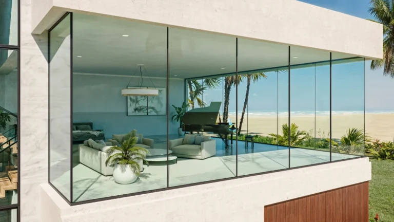
The evolution of the contemporary building envelope has elevated the glass pane from a simple, non-structural space divider into a major load-bearing material. High-end real estate and institutional buildings across the United States increasingly rely on large expanses of highly transparent glass to connect internal spaces with the exterior environment. Luxury Architectural Glass America. Achieving these designs requires extreme engineering precision and a thorough understanding of material science.
Designers and engineers working with heavy glazing face the challenge of balancing structural integrity with optical clarity and thermal performance. Thick, multi-layered glass makeups must resist severe environmental loads while remaining free from internal distortion or optical imperfections. Knowing how to select and detail these advanced materials requires cross-disciplinary coordination between structural engineers, glass temperers, and specialty installation contractors.
To ensure long-term performance and financial control, project teams must look past basic compliance metrics to analyze physical constraints and loading histories. This comprehensive reference document explores the engineering mechanics, system variations, testing methodologies, and economic variables that govern structural residential and commercial glazing. By exploring the physical behavior of building systems, this guide provides a systematic methodology for specifying assets that remain efficient over their design life.
Understanding “luxury architectural glass america”
When professionals investigate luxury architectural glass america, they must treat the building facade as an integrated thermodynamic system rather than a collection of independent panels. The goal is to design an envelope that maximizes visual transparency while minimizing the need for expensive, custom-fabricated glass makeups or heavy, unnecessary steel bracing.
A common pitfall in modern design is the assumption that adding more layers of glass will solve any structural problem or thermal performance challenge. In reality, over-insulating or over-specifying glass thickness without providing adequate structural support or solar control can trap heat inside the building, driving up cooling energy consumption. The selection of the correct system depends directly on the system’s stress profile and the surrounding support structure.
To ensure long-term performance, design and construction teams must look beyond the visual rendering and analyze the physics of the system. Unlike traditional residential construction materials such as timber, steel, or reinforced concrete, glass is an elastic-brittle material. It does not yield before failure, which means that any design oversight, edge imperfection, or installation flaw can lead to sudden and total rupture.
Deep Contextual Background: System Evolution
The development of load-bearing glass design began in earnest with the invention of the float glass process in the mid-twentieth century. Before this innovation, glass was produced in smaller sizes with significant optical distortion and inconsistent thickness profiles. Landmark buildings in major US cities demonstrated the potential of the hung glass facade. These International Style buildings used lightweight skins of aluminum and glass, but the glass itself remained non-load-bearing, supported by a heavy steel or concrete floor plate assembly.
The 1970s and 1980s saw a shift toward performance and structural independence. The introduction of insulating glass units (IGUs) and low-emissivity (Low-E) coatings transformed the building skin into an environmental filter. Designers began experimenting with ways to eliminate exterior metal supports. Engineers developed point-supported glazing systems, such as the planar fitting assembly, which transfer wind loads from the glass surface through articulated stainless steel nodes directly to secondary support structures like glass fins or tension trusses.
In the twenty-first century, the evolution of high-strength structural interlayers has turned the glass pane into a composite structural material. Using ionoplast and specialized polyvinyl butyral (PVB) interlayers allows multiple lites of glass to act as a unified section, retaining residual load-bearing capacity even after one lite fractures. Today, advanced projects specify closed-cavity facades (CCFs) and active skins that respond to external weather conditions. These designs require highly complex structural plans that integrate sensors, dynamic coatings, and structural silicone joints.
Conceptual Frameworks and Design Models
To analyze the structural performance of an envelope, engineers use specific mental models and analytical frameworks:
-
The Stress Distribution and Concentration Model: This model treats the glass lite as a brittle membrane and models the stress concentrations around holes, notches, and bolted connections. It requires the designer to ensure that local peak stresses remain below the material’s design capacity.
-
The Post-Breakage Residual Capacity Framework: This model assumes that one or more lites within a laminated assembly will break. It calculates the load-bearing capacity of the remaining intact lites and the interlayer to prevent catastrophic collapse.
-
The Thermal-Bridge and Deflection Matrix: This model evaluates the thermal performance and deflection characteristics of the structural assembly under wind and gravity loads. It optimizes the balance between maximum transparency and frame deflection.
Key Categories or Variations
To select the most appropriate system, designers compare variations based on their structural support mechanisms, interlayer technology, and intended application in modern properties.
Comparison of Structural Glass Systems
System selection requires a rigorous analysis of environmental and structural loads. For example, an engineer designing a high-capacity structural fin in a seismic zone would specify a laminated ionoplast system. The ionoplast interlayer provides high shear stiffness, allowing the fin to carry large bending moments without excessive deflection. In contrast, for a balustrade that requires high impact resistance but less structural rigidity, a standard laminated PVB assembly is often sufficient.
Detailed Real-World Scenarios Luxury Architectural Glass America
The practical execution of structural glass plans depends on local constraints, climatic exposures, and building geometries.
Scenario A: The Long-Span Glass Fin Wall
A two-story residential living room requires a highly transparent, 24-foot-tall glass wall without intermediate vertical steel columns. The wall must resist a high wind load of 40 pounds per square foot while limiting the horizontal deflection of the glass fins to prevent the silicone joints from tearing.
-
Decision Point: Choosing between a laminated tempered glass fin and a laminated ionoplast structural fin.
-
Analysis of Options:
-
Option 1 (Laminated Tempered): Under wind load, the PVB interlayer in the laminated tempered fin shears, leading to large deflections and potential edge rotation at the fixing nodes.
-
Option 2 (Laminated Ionoplast): The ionoplast interlayer transfers shear forces efficiently between the lites, keeping the deflection within the allowable limits of the structural silicone sealant.
-
-
Second-Order Effect: The high stiffness of the ionoplast fin places greater reaction loads on the concrete floor slabs, requiring the design of stronger embedded steel anchors.
Scenario B: The Sloped Glass Skylight
A large, sloped skylight over a residential indoor pool must support both live maintenance loads and snow loads. The design must ensure that if a maintenance worker drops a tool or if the glass breaks under a snow load, the glass fragments do not fall onto the space below.
-
Decision Point: Using a monolithic heat-strengthened lite versus a laminated assembly with an ionoplast or PVB interlayer.
-
Analysis of Options:
-
Option 1 (Monolithic Tempered): If broken, tempered glass shatters completely into small dice that fall through the opening, creating an unacceptable life-safety hazard.
-
Option 2 (Laminated Assembly): The laminated configuration retains the broken glass fragments on the interlayer, providing a secondary safety barrier that protects the pool area below.
-
Scenario C: The Structural Glass Floor
A modern residential mezzanine features a floor supported by structural steel beams. The floor must support heavy pedestrian live loads while maintaining a non-slip surface and absolute structural integrity without excessive vibration.
-
Decision Point: Specifying a three-lite laminated ionoplast makeup versus a two-lite laminated tempered makeup.
-
Analysis of Options:
-
Option 1 (Two-Lite Makeup): The failure of one lite leaves only a single lite to carry the live load, resulting in a low factor of safety and noticeable deflection under foot traffic.
-
Option 2 (Three-Lite Makeup): The three-lite makeup provides a redundant load path. If the top sacrificial lite breaks, the remaining two lites continue to carry the full design load with an adequate safety factor.
-
Scenario D: The Four-Sided Point-Supported Canopy
An exterior structural glass canopy extends 6 feet from the face of a modern home and is supported by four stainless steel rods. The canopy experiences continuous dynamic wind uplift and dead-load bending moments at the bolt locations.
-
Decision Point: Choosing between a countersunk point-fixing node and a through-bolted assembly with a neoprene washer.
-
Analysis of Options:
-
Option 1 (Countersunk Point-Fixing): Countersunk bolts create high localized shear stresses within the glass hole, leading to crack initiation under cyclic wind uplift.
-
Option 2 (Through-Bolted Assembly): The through-bolted assembly spreads the bearing load over a larger area and uses an elastomeric washer to isolate the glass from direct metal contact.
-
Planning, Cost, and Resource Dynamics
The financial framework of structural glass projects is sensitive to the design, specification, and fabrication processes. Overspecification often leads to significant cost premiums without measurable improvements in performance.
Estimated Cost Variance by Assembly Type
Opportunity costs are prevalent in this market. Choosing large-format glass lites often requires specialized hoisting equipment and street closures during installation. Furthermore, if a lite breaks during construction, the replacement lead time for custom-tempered or bent glass can delay the entire project schedule by several months.
Tools, Strategies, and Support Systems
To design with the best options, facade engineers use several analytical and testing platforms:
-
Finite Element Analysis (FEA) Software: Programs such as ANSYS or SAP2000 model the stress concentrations around holes and calculate the deflection of complex glass shapes under load.
-
LBNL Window/Therm Software: Used to determine the center-of-glass and overall U-values, solar heat gain coefficients, and condensation resistance index of the assembly.
-
Heat-Soak Ovens: A quality-control process that exposes tempered glass to elevated temperatures to force the failure of lites with nickel-sulfide inclusions before they are shipped to the site.
-
Acoustic Testing Chambers: Used to verify the sound transmission class (STC) rating of the structural assembly in noisy residential environments.
-
Wind Tunnel Testing: Physical models tested in boundary-layer wind tunnels to determine localized peak pressures on complex canopies and wall systems.
-
Full-Scale Structural Mock-Ups: A 1:1 scale test of the connection details and glass lites to confirm the performance of the system before mass production.
The Risk Landscape: Structural Vulnerabilities and Failure Modes
Understanding the risk landscape and identifying the compounding failure modes is critical to specifying structural glazing makeups accurately.
-
Nickel Sulfide (NiS) Inclusions: Microscopic impurities in float glass that can expand over time, causing tempered glass to shatter spontaneously without an external load. Specifying heat-soak testing significantly reduces this risk.
-
Edge Delamination: The separation of the interlayer from the glass along the perimeter, caused by exposure to moisture or UV radiation, which weakens the composite action of the laminated makeup.
-
Thermal Stress Fracture: Breakage caused by a temperature differential between the hot, sun-exposed center of the glass and the cool, frame-shaded edge.
-
Silicone Reversion: The chemical degradation of structural silicone joints caused by incompatibility with adjacent setting blocks or cleaning solvents.
Governance, Maintenance, and Long-Term Adaptation
Structural glass systems require an active maintenance program to achieve their target lifespan of 30 to 50 years.
The Layered Maintenance Checklist
-
Bi-Annually: Wash the glass and inspect the exterior silicone seals for signs of cracking or detachment.
-
Every Five Years: Perform a detailed pull-test or inspection of the structural silicone joints and mechanical nodes.
-
Replacement Triggers: Replace any insulating glass unit that shows signs of internal condensation, which indicates a failure of the primary edge seal.
-
Documentation and Records: The facility manager must maintain a digital log of the makeup, batch number, and installation location of every glass lite.
Measurement, Tracking, and Evaluation
Assessing the performance of a structural glass system requires both quantitative and qualitative methods:
-
Leading Indicators: Real-time data from strain gauges attached to the glass fins or nodes, measuring deflection and stress during high wind events.
-
Lagging Indicators: The frequency of spontaneous glass breakage or the increase in overall building cooling loads due to seal failure.
-
Documentation Examples:
-
Digital Twins: A model tracking every glass lite, its material properties, and its location on the building.
-
Calibration Reports: Records verifying the bolt torque applied to all countersunk connections during assembly.
-
As-Built Dimensional Surveys: Measurements comparing the structural frame to the glass fabrication tolerances.
-
Common Misconceptions and Oversimplifications
-
Myth: All structural glass is equally strong.
-
Correction: The strength of an assembly depends on the heat treatment (tempered vs. annealed) and the composite action of the interlayer.
-
-
Myth: PVB and Ionoplast interlayers can be used interchangeably.
-
Correction: Ionoplast interlayers are significantly stiffer and transfer shear forces more effectively, making them necessary for long-span structural fins.
-
-
Myth: Glass has a ductile yield phase.
-
Correction: Glass is a purely elastic, brittle material that fails without warning when its tensile stress limit is exceeded.
-
-
Myth: Toughened glass is free from imperfections.
-
Correction: Toughened glass can contain nickel-sulfide inclusions that lead to spontaneous breakage.
-
-
Myth: Structural glazing silicone acts as a simple weather seal.
-
Correction: Structural silicone transfers lateral loads to the frame and must be designed with an adequate structural bite.
-
Ethical and Contextual Considerations
The specification of load-bearing glass assemblies involves significant sustainability and ethical responsibilities. The production of float glass and the energy-intensive heat-treating process generate substantial embodied carbon. Engineers and designers should balance the desire for transparency with the need for low-energy consumption over the building’s lifecycle.
Furthermore, transparent glass facades present a significant hazard to migratory bird populations. Ethical design considerations require the integration of fritted patterns, acid-etched designs, or ultraviolet-reflective coatings that make the glass visible to birds without compromising the structural integrity or performance of the envelope.
Synthesis and Editorial Perspective
The creation and execution of structural glazing makeups require technical discipline, attention to detail, and intellectual honesty. A high-performance structural glass assembly is a complex composite that must be engineered to withstand the effects of wind, thermal expansion, and mechanical loads.
As we continue to push the boundaries of transparency in modern residential architecture, the safety and performance of these systems will depend on our ability to manage the material’s properties. By understanding the interaction between glass chemistry, interlayers, and support hardware, designers can create structures that are both light and durable.