Common Glass Structural Mistakes: A Definitive Engineering Guide
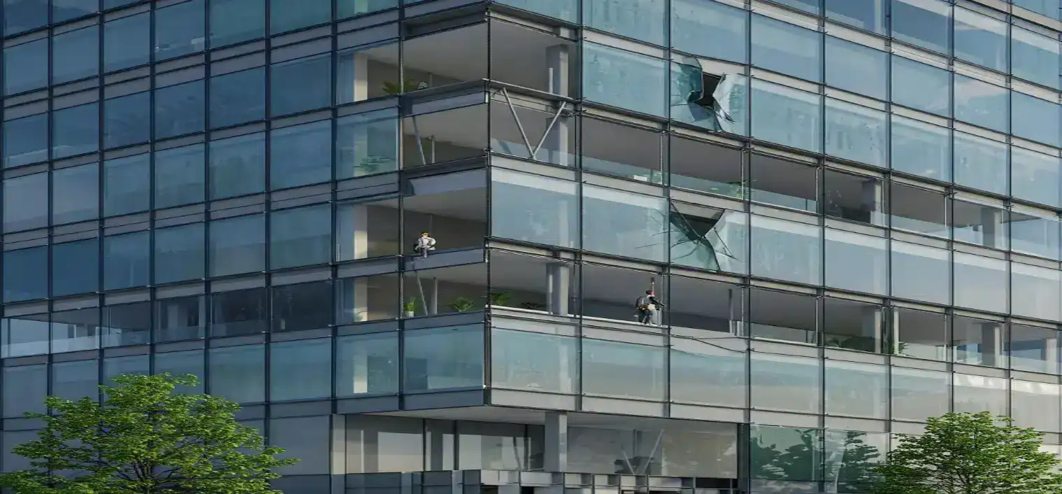
The evolution of modern architecture is defined by an ongoing pursuit of transparency. Glass has transformed from a fragile, punctured infill material into a primary, load-bearing component of the building envelope. This transformation requires a fundamental shift in how structural engineers and facade consultants approach material selection, load distribution, and environmental interfaces. Common Glass Structural Mistakes. When designers attempt to push the limits of scale and slenderness without adequate analytical rigor, the results can be structurally and financially catastrophic.
Understanding the structural behavior of glass requires an appreciation of its brittle nature. Unlike structural steel or reinforced concrete, which exhibit yielding and plastic deformation prior to failure, annealed and heat-treated glass behaves elastically until the moment of rupture. This lack of ductility means that design oversights or installation flaws can result in sudden and total collapse. The margin for error in glass engineering is exceptionally small, and minor oversights during the detailing phase can become major structural failures under extreme environmental loads.
To ensure long-term performance, design and construction teams must look past the visual rendering and analyze the physics of the system. This comprehensive analysis explores the most prevalent pitfalls in modern facade engineering. By dissecting the root causes of these vulnerabilities, structural professionals can better anticipate extreme events, select appropriate safety factors, and ensure that the constructed envelope performs as intended over its entire design life.
Understanding “common glass structural mistakes”
The phrase common glass structural mistakes encompasses a wide array of errors made during the design, specification, fabrication, and construction phases of a building project. These errors generally stem from a fundamental misunderstanding of glass as an isotropic, brittle material that is highly sensitive to stress concentrations, edge quality, and environmental temperature fluctuations. When structural engineers apply traditional steel or concrete design philosophies to glass without modification, the likelihood of systemic failure increases dramatically.
A significant misunderstanding during the early conceptual phase is the assumption that point-supported glass systems or frameless glass walls behave like continuous, ductile plates. Failing to model these small geometric interfaces can lead to spontaneous glass breakage under standard wind-load cycles.
Another oversimplification occurs when teams fail to account for long-term material degradation and environmental interaction. These oversights result in progressive detachment under dynamic loads. Identifying the most common glass structural mistakes requires a multidisciplinary perspective that bridges the gap between chemical adhesion, structural mechanics, and architectural geometry.
Deep Contextual Background: The Evolution of Structural Glass
The development of structural glass systems began in earnest during the mid-twentieth century with the rise of the modern curtain wall. Early designs relied on punched window configurations punched into thick masonry facades. As manufacturing techniques improved, the ability to produce large, flat lites of float glass allowed architects to maximize natural light and visual connection to the outdoors. However, these early configurations were structurally separate from the building’s primary gravity and lateral force-resisting systems.
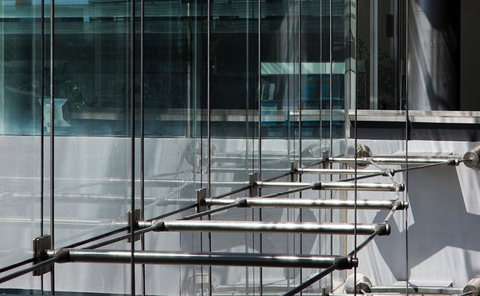
The transition from supported glazing to structural glass occurred in the late 1970s and 1980s, pioneered by European engineers and architects who sought to eliminate opaque frames. This era saw the introduction of point-supported systems, where stainless steel patch plates and articulated bolts transferred wind loads directly to secondary support structures such as glass fins or tension trusses. The use of glass as a load-bearing material required new design standards, as engineers had to address the random nature of micro-cracks on the material’s surface.
Throughout the late twentieth and early twenty-first centuries, the development of high-strength structural interlayers and computer-aided engineering tools transformed the discipline. Laminated glass made it possible for an envelope to carry loads even after the fracture of an individual glass lite. Despite these technological leaps, the fundamental material properties remained unchanged. Today, the rush toward taller, more slender facades has outpaced the understanding of these systems in many design offices, leading to repeated errors in edge preparation and thermal movement calculations.
Conceptual Frameworks and Mental Models for Design
To analyze structural performance, experienced engineers use several specific conceptual frameworks and mental models:
-
The Stress-Concentration Gradient Model: This framework models how loads transfer through holes, notches, and edges. It assumes that any discontinuity in the glass surface multiplies the local stress, requiring an evaluation of both the nominal and peak stresses within the lite.
-
The Thermal-Bridge Continuum: This model views the building envelope as a thermodynamic engine. It focuses on the difference in temperature between the center of the glass lite and the edge captured by the frame, calculating the resulting tensile stresses that can lead to thermal fracture.
-
The Redundancy/Fail-Safe Logic: This model analyzes system behavior after a failure occurs. It assesses whether the collapse of a single pane will lead to progressive failure or if the load can be safely transferred to adjacent components.
Key Categories of Structural Failures
Analyzing the failures that occur in architectural glass systems reveals several recurring categories of design and construction oversights. Each category is characterized by a unique mechanism of material behavior and environmental interaction.
Classification of Structural Vulnerabilities
| Category | Primary Mechanism | Consequence | Prevention Strategy |
| Edge Damage & Fabrication Errors | Micro-cracks on the glass perimeter | Spontaneous breakage | Polishing, heat-soak testing |
| Improper Edge Clearance | Glass-to-metal contact | Edge crushing and cracking | Adequate bite and setting blocks |
| Constrained Thermal Expansion | Inadequate expansion gaps | Thermal stress fracture | Proper bite and joint sizing |
| Misapplied Bolt Torques | Excessive pressure on point fixings | High local shear stress | Torque-limiting fittings |
| Incompatible Sealant Chemistry | Plasticizer migration in silicone | Loss of adhesion | Laboratory compatibility testing |
| Wind-Load Fatigue | Cyclic loading beyond capacity | Delamination and fatigue | Lamination, thicker lites |
| Deflection Over-Constraint | Rigid capture of moving elements | High local bending stress | Slotted holes, sliding pins |
Edge Damage and Fabrication Errors
The edge quality of glass lites is a major factor in determining its load-bearing capacity. During the cutting and seaming process, microscopic flaws and micro-cracks are inevitably introduced along the perimeter of the lite. If the edge work is poor—such as leaving “shell chips” or unpolished, rough edges—these small flaws act as stress concentration points. Under the influence of sustained tensile stresses caused by wind loads, these cracks can propagate, leading to sudden and unexpected failure.
Preventing this vulnerability requires strict specifications for edge finishing, including seaming or full polishing of all exposed edges. In addition, for heat-strengthened and fully tempered glass, the process must be carefully controlled to prevent optical distortion and uneven cooling profiles, which can lock in residual tensile stresses.
Improper Edge Clearance and Bite
Another vulnerability occurs when the glass edge comes into contact with the surrounding metal frame. Glass expands and contracts at a different rate than steel or aluminum. If the edge clearance is too small or missing entirely, temperature changes cause the glass to bear directly against the metal frame. This contact results in point loading, which initiates a fracture originating at the perimeter of the lite.
Designers must specify setting blocks and maintain adequate edge clearance around the perimeter of the glass.
Constrained Thermal Expansion
Glass facades are subjected to extreme temperature variations, ranging from sub-zero winter winds to intense summer solar radiation. This temperature differential across a single pane creates localized expansion.
If the edge of the lite is rigidly fixed or if the bite (the depth of the glass captured within the frame pocket) is too deep, the tensile stress at the edge can exceed the modulus of rupture. This leads to a thermal stress fracture that propagates across the pane. To mitigate this risk, structural glazing plans must specify appropriate dimensions for edge clearances and avoid over-constraining the glass within deep, uninsulated frame pockets.
Misapplied Bolt Torques in Point-Supported Systems
Point-supported glass systems transfer dead loads and wind loads through drilled holes in the glass, utilizing countersunk bolts or articulated nodes. One of the most common glass structural mistakes is the over-tightening of these bolts during installation. When an installer applies excessive torque, it creates high localized shear and bearing stresses around the hole.
These stresses, combined with the normal dynamic loads from wind, can cause the glass to crack at the hole perimeter. To prevent this, the hardware must include elastomeric or nylon washers that isolate the glass from direct metal-to-metal contact. Furthermore, installation crews must use torque-limiting wrenches to ensure that the specified pressure is not exceeded.
Incompatible Sealant Chemistry
Structural glazing systems rely on structural silicone to transfer wind loads from the glass to the support frame. A common oversight in the specification phase is the assumption that all silicones are chemically compatible with all substrates.
This chemical incompatibility can lead to the migration of plasticizers from the setting blocks or adjacent weather seals into the structural silicone, causing it to lose its adhesion and mechanical properties. This degradation can result in the progressive detachment of the glass lite under wind suction loads. Engineers must require contact area and compatibility testing for all materials before construction begins.
Wind-Load Fatigue and Deflection Limits
Tall buildings experience dynamic, pulsating wind loads that create cyclic stress within the facade elements. If the glass is too thin or if it is not supported along enough edges, it will undergo significant deflection under high wind speeds. This deflection can cause the glass to impact adjacent decorative elements or, over time, cause fatigue in the silicone joints.
Furthermore, excessive deflection can cause the edges of the glass to slip out of the structural bite of the frame. To prevent this, structural calculations must account not only for the peak wind pressure but also for the deflection limits (L/60 or L/100, depending on the system type) to ensure the integrity of the weather and structural seals.
Deflection Over-Constraint
When glass is supported by a flexible structure such as a cable-net wall or a large-span steel truss, the support structure deflects under lateral loads. If the connection between the glass and the support structure is too rigid, the deflection of the truss places unintended bending and shear stresses on the glass panels.
To prevent this, the connections must include slotted holes, sliding pins, or neoprene-damped fixings that allow the support structure to deflect without transferring those stresses directly into the glass.
Detailed Real-World Scenarios and Decision Logic Common Glass Structural Mistakes
To understand the practical consequences of these oversights, it is helpful to analyze several real-world scenarios involving structural design and construction decisions.
Scenario A: The Supertall Spandrel Zone
A 60-story corporate headquarters located in a coastal metropolitan area experiences an unexpectedly high rate of glass breakage on its spandrel panels.
-
The Constraint: The spandrel panels are made of fully tempered, heat-absorbing monolithic glass placed directly in front of uninsulated backup walls.
-
Decision Point: Should the engineering team replace the broken panes with identical units, or redesign the spandrel zone to accommodate thermal movement?
-
Analysis of Options:
-
Option 1 (Identical Replacement): Replacing the panels without changes will result in continued breakage, as the root cause (high thermal stress due to shading) remains unaddressed.
-
Option 2 (Heat-Soaking and Edge Polishing): While heat-soaking reduces the risk of spontaneous breakage from nickel-sulfide inclusions, it does not resolve the thermal stress issue.
-
Option 3 (Redesign with Edge Clearance and Insulation): The team chooses to redesign the panels with polished edges and adequate expansion gaps, along with the addition of insulation behind the panel to reduce the temperature gradient.
-
-
Second-Order Effect: The new design requires an adjustment to the spandrel framing, slightly increasing the visual shadow line of the floor slabs.
Scenario B: Point-Supported Atrium Facade
A 40-foot-tall atrium wall uses a point-supported glass system with countersunk bolts. During a winter storm, several panes crack around the bolt holes.
-
The Constraint: The installation crew tightened the bolts using pneumatic tools to ensure a weather-tight fit, exceeding the design torque specifications.
-
Decision Point: Should the maintenance team retorque the bolts or replace the cracked lites?
-
Analysis of Options:
-
Option 1 (Retorque the Bolts): This option is unsafe, as micro-cracks have already formed around the bolt holes. Retorquing will accelerate catastrophic failure.
-
Option 2 (Replace the Damaged Lites): The team replaces the lites and implements a strict torque-control protocol using hand tools and calibrated wrenches with torque-limiting mechanisms.
-
-
Failure Mode Analysis: The failure was caused by the combination of localized bearing stress and the thermal contraction of the glass during cold weather.
Scenario C: The Cable-Net Lobby Entrance
A high-end retail lobby features a 30-foot tall cable-net wall with point-supported fittings. After high wind events, the glass rattles and the silicone joints show signs of tearing.
-
The Constraint: The cable-net system is too flexible, allowing deflections of up to L/45, which exceeds the flexibility limits of the structural silicone bite.
-
Decision Point: Stiffen the cable-net structure or replace the glass with thicker, laminated lites.
-
Analysis of Options:
-
Option 1 (Thicker Glass): Thicker glass increases the load on the cables, which may cause the structure to deflect further.
-
Option 2 (Stiffen the Support Structure): The engineering team chooses to increase the pretension in the cables and install secondary dampers to limit deflection under wind loads.
-
-
Second-Order Effect: Increasing the pretension in the cables requires reinforcing the surrounding concrete columns and floor slabs to handle the higher reaction loads.
Scenario D: The Unitized Facade with Concealed Joints
A new residential tower uses a unitized curtain wall system with 4-sided structural silicone joints. During inspection, several units show signs of sealant peeling away from the aluminum frame.
-
The Constraint: The factory-applied structural silicone was applied when the aluminum was covered in a light film of manufacturing oil.
-
Decision Point: Strip and reglaze all units on-site, or remove the facade panels and reglaze them in the factory.
-
Analysis of Options:
-
Option 1 (On-Site Reglazing): It is difficult to achieve the required quality control for surface preparation and silicone curing on-site due to weather exposure.
-
Option 2 (Factory Reglazing): The team removes the units and returns them to the factory for proper solvent cleaning and reapplication of the structural silicone.
-
-
Compounding Risk: The delay in construction leads to exposure of the unfinished interior to rain, causing damage to the drywall and flooring.
Scenario E: The Cold-Bent Glass Canopy
A dramatic, sweeping glass canopy uses cold-bent, laminated glass lites to create a curved surface.
-
The Constraint: The glass is bent beyond its elastic limit during installation, placing permanent tensile stresses on the interlayer and the outer lite.
-
Decision Point: Maintain the design and accept the high risk of spontaneous breakage, or modify the radius of the canopy.
-
Analysis of Options:
-
Option 1 (Accept the Risk): The risk of glass falling on pedestrians is unacceptable from a life-safety perspective.
-
Option 2 (Modify the Geometry): The team modifies the canopy to use smaller, flat or slightly bent panels within the elastic limits of the glass.
-
-
Second-Order Effect: The change in geometry alters the architectural appearance of the canopy, requiring a redesign of the drainage and flashing details.
Planning, Cost, and Resource Dynamics
The financial architecture of a facade project is sensitive to design oversights. When common glass structural mistakes are corrected during the construction phase, the costs can be many times higher than if the issue had been caught during the early engineering review.
Estimated Cost Variance of Remediation
| Phase of Discovery | Cost Factor (Multiplier) | Primary Cost Drivers |
| Concept / Design Phase | 1.0x | Additional FEA engineering, minor drafting changes |
| Fabrication Phase | 3.0x – 5.0x | Remanufacturing of lites, modified extrusion dies |
| Construction Phase | 10.0x – 20.0x | Crane rentals, site delays, rework of adjacent trades |
| Post-Occupancy Phase | 50.0x+ | Litigation, scaffolding, facade replacement, loss of rent |
Opportunity costs are often found in the logistics of the schedule. If an entire floor of the building is delayed because a custom-tempered panel must be remanufactured, the delay ripples through the timeline of all interior and exterior trades.
Tools, Strategies, and Technical Support Systems
To avoid these pitfalls, modern facade engineering relies on a suite of simulation and quality control tools:
-
Finite Element Analysis (FEA) Platforms: Software such as ANSYS or SAP2000 allows engineers to model the stress distribution within glass lites around holes and complex geometries.
-
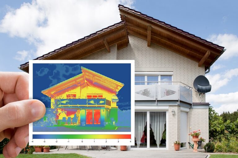
Thermographic Analysis Tools: Software used to simulate the temperature gradient across the cross-section of an IGU to prevent thermal breakage.
-
Third-Party Laboratory Testing: Facilities such as the AAMA or CWCT test walls for air infiltration, water penetration, and dynamic structural loading.
-
Heat-Soak Ovens: Used to subject fully tempered glass to elevated temperatures, causing panes with nickel-sulfide inclusions to fail in the factory rather than on-site.
-
Torque Calibration Systems: Digital data loggers used on-site to verify the torque applied to every point-fixing bolt.
-
3D Laser Scanning: Used to survey the “as-built” concrete frame, allowing the fabrication dimensions to be adjusted before the glass arrives on-site.
Risk Landscape and Compounding Failures
Failures in structural glass design are rarely the result of a single event; they are usually the result of compounding vulnerabilities.
For example, if a hole in the glass is drilled with a small defect on its inside surface, and the installer over-tightens the bolt, the two vulnerabilities work together. The high localized bearing stress from the bolt, acting on the stress concentration from the drilling defect, creates a situation where a normal gust of wind can cause the glass to fail.
The risk landscape is also complicated by the division of responsibilities. In many projects, the design of the glass and framing is “delegated” to the specialty subcontractor. If the design engineer does not communicate the specific edge clearance requirements to the installation crew, a high-quality glass pane can be ruined by poor field placement.
Governance, Maintenance, and Long-Term Adaptation
A structural glass facade requires a formal governance structure and a dedicated maintenance schedule to achieve its intended 30-to-50-year design life.
Layered Maintenance Checklist:
-
Quarterly Inspections: Inspect all gaskets and silicone seals for signs of cracking, peeling, or loss of adhesion.
-
Bi-Annual Cleaning: Wash the glass using deionized water and non-abrasive cleaners. Avoid strong alkaline or acidic solutions that can etch the surface or degrade the silicone.
-
Five-Year Structural Review: Perform a detailed inspection of all point-supported nodes and inspect the edge bite across a representative sample of the facade.
-
Trigger Event Response: Any seismic event or windstorm exceeding the design basis of the building requires a post-event survey of the entire facade, with special attention given to points of connection.
Measurement, Tracking, and Evaluation
Evaluating the success of a glass structure involves tracking both leading and lagging indicators:
-
Leading Indicators: Deflection readings during high wind events; analysis of manufacturing defects found during quality assurance audits at the factory.
-
Lagging Indicators: The frequency of glass breakages; the appearance of condensation or clouding within insulated glazing units.
-
Documentation Examples:
-
The Glass Log: A database tracking the tempering, laminating, and delivery of each lite.
-
Torque Calibration Reports: Digital records showing the torque values applied to each node during installation.
-
As-Built Surveys: 3D models comparing the real structure with the fabrication drawings to ensure clearances.
-
Common Misconceptions and Oversimplifications
-
Myth: Fully tempered glass is unbreakable.
-
Correction: Fully tempered glass is strong against bending, but it is highly sensitive to edge impacts and can shatter spontaneously due to internal inclusions like nickel sulfide.
-
-
Myth: All structural silicone is the same.
-
Correction: Structural silicone must be specified by chemical type and tested for compatibility with all adjacent materials.
-
-
Myth: Glass has no deflection limits.
-
Correction: Glass must be designed to limit deflection to maintain the integrity of seals and avoid edge pull-out.
-
-
Myth: Point-supported glass is frameless and simple.
-
Correction: Point-supported glass requires complex hardware and thicker glass lites to handle stress concentrations around the fixings.
-
-
Myth: Annealed glass is safe for modern facades.
-
Correction: Annealed glass breaks into large, sharp pieces and should not be used in high-altitude, high-wind, or high-impact areas.
-
-
Myth: Thermal stress is only an issue in cold climates.
-
Correction: Thermal stress is a problem whenever there is a temperature gradient across a panel, which occurs in both hot and cold climates depending on shading.
-
Ethical and Contextual Considerations
The use of structural glass facades has significant sustainability and ethical implications. Glass manufacturing is an energy-intensive process, and recycling complex, laminated, or coated glass is difficult. An ethical approach to design requires specifying products that maximize energy efficiency, reduce life-cycle operating costs, and utilize durable materials.
Furthermore, building design must consider the impact of transparency on bird populations. The reflection of trees and sky on glass facades causes millions of bird strikes each year. Modern building codes are increasingly requiring that envelopes include frit patterns, ultraviolet coatings, or external shading devices that make the glass visible to birds without obscuring the view from within.
Synthesis and Final Editorial Perspective
The design and construction of structural glass systems demand intellectual honesty, patience, and strict engineering discipline. The history of facade failures shows that most issues are not caused by the weakness of the material itself, but by common glass structural mistakes made during the design and construction phases. Understanding the limits of the material allows engineers to create envelopes that are both transparent and safe.
The future of the building skin lies in intelligent design, where the interface between glass, frame, and structure is fully coordinated. As we move toward a carbon-neutral built environment, the measure of a successful facade will no longer be how invisible it appears, but how well it performs over the life of the building. The mastery of these details is what separates a short-term architectural trend from an enduring work of engineering.